To reduce cavitation risk, keep adequate pressure at the pump inlet, control suction-pipe losses, avoid unsuitable high-flow operation, account for liquid temperature and maintain enough submergence. Check the actual pump curve and NPSH requirement at the intended duty point.
01 / DEFINITION
What pump cavitation actually is
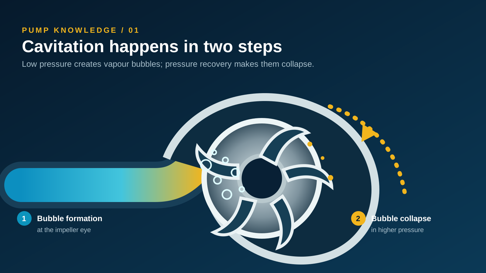
Every liquid has a vapour pressure. If the local absolute pressure inside the pump falls below that vapour pressure, a small portion of the liquid can change into vapour and form bubbles. In a centrifugal pump, this often begins near the impeller eye, where the liquid accelerates and pressure is low.
The bubbles then travel with the liquid into a region of higher pressure. Their collapse releases highly localised energy. Repeated collapse near an impeller or casing surface can create pitting, vibration, noise and a gradual loss of hydraulic performance.
Air entering through a suction leak is not the same physical process as cavitation. Air ingress, vortexing and cavitation can sound similar, however, and more than one may occur at the same time.
02 / WARNING SIGNS
What an operator may notice
Gravel-like noise
A crackling or rattling sound near the hydraulic end is a common warning, but it should not be used as the only diagnosis.
Vibration changes
Vibration may rise or become unstable as bubble formation and collapse disturb the flow entering the impeller.
Unstable flow or head
Measured discharge pressure and flow can fluctuate or fall below the expected pump curve.
Surface pitting
After inspection, the impeller or casing may show rough, crater-like erosion in affected regions.
Other faults can produce similar symptoms: a damaged bearing, misalignment, loose mounting, entrained air, debris at the impeller, an incorrect rotation direction or an electrical problem. Diagnosis should compare operating data with physical inspection instead of relying on sound alone.
03 / SUCTION CONDITIONS
Why the pressure at the inlet becomes too low
| Condition | Why it matters | What to verify |
|---|---|---|
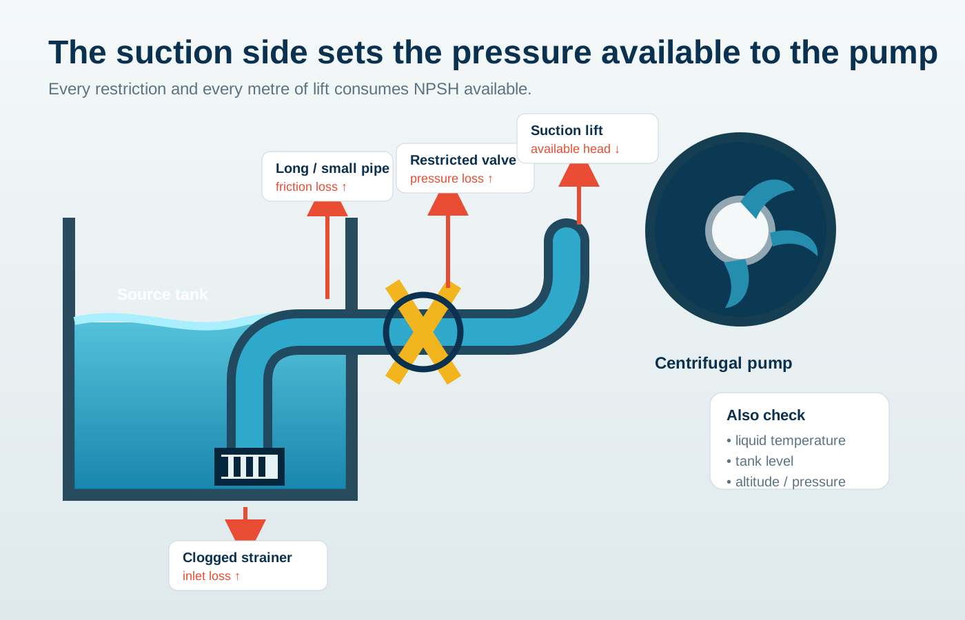
| Low source level or excessive suction lift | Less static pressure reaches the inlet. | Minimum liquid level, pump elevation and seasonal variation. |
| Undersized, long or complex suction pipe | Friction and fitting losses increase with flow. | Internal diameter, length, elbows, valves and actual flow. |
| Blocked strainer or partly closed valve | A local restriction consumes inlet pressure. | Strainer condition, valve position and pressure before the pump. |
| High liquid temperature | Vapour pressure rises as the liquid becomes hotter. | Normal and maximum operating temperature. |
| Operation too far to the right of the curve | High flow can increase inlet velocity and NPSH required. | Measured duty point against the manufacturer’s curve. |
| Insufficient submergence or inlet vortex | Disturbed inflow may lower local pressure and entrain air. | Water depth above the inlet, sump geometry and vortexing. |
04 / NPSH
The selection check behind the diagnosis
NPSH available (NPSHa) describes the pressure head the system can provide above the liquid’s vapour pressure at the pump inlet. NPSH required (NPSHr) is determined from pump testing and varies with flow. A suitable installation needs NPSHa above NPSHr with an appropriate margin for the application and applicable guidance.
All terms must use consistent head units and absolute pressure. Altitude, tank pressure and liquid temperature can change the result.
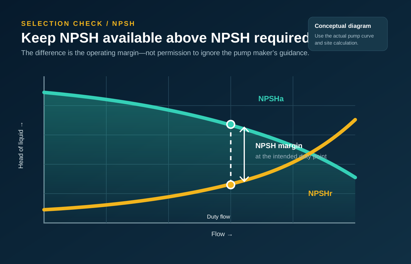
NPSHr is not one fixed number for an entire pump series. It must be checked at the intended flow and for the selected speed, impeller and configuration. Catalogue information is a starting point; the purchase specification should identify the actual duty and test basis.
05 / DIAGNOSIS
A practical sequence before changing the pump
- 01
Record the symptom and operating point
Measure flow, suction pressure, discharge pressure, liquid level, temperature, speed or frequency, voltage and current. Note when the noise begins.
- 02
Compare the duty point with the curve
Confirm that the installed pump, impeller and speed match the documentation. Check whether the system is operating at a much higher flow than intended.
- 03
Inspect the complete inlet path
Check the strainer, suction valve, pipe diameter, fittings, air leaks, liquid level, inlet submergence and any vortex at the intake.
- 04
Calculate NPSHa at the worst condition
Use the lowest source level, highest expected temperature, actual elevation and realistic pipe losses—not only the best operating condition.
- 05
Separate cavitation from mechanical faults
Inspect bearings, alignment, mounting, rotation and the impeller. If possible, compare vibration and pressure data before and after a controlled system change.
06 / PREVENTION
Changes that can increase inlet pressure or reduce demand
- Reduce suction lift: lower the pump or raise the minimum liquid level when the installation allows it.
- Reduce suction losses: use an adequate pipe diameter, shorten the route and remove unnecessary fittings.
- Remove restrictions: clean strainers, fully open the correct isolation valve and check for a collapsed hose or blocked inlet.
- Control the operating point: verify system resistance and avoid running outside the pump’s intended flow range.
- Account for temperature: recalculate vapour-pressure head for the hottest liquid condition.
- Improve sump inflow: provide adequate submergence and address vortices or uneven approach flow.
- Select a more suitable hydraulic configuration: review speed, impeller, pump size and NPSHr with the supplier.
Throttling the discharge, changing speed or replacing the pump may alter the duty point, but the safe action depends on the equipment and system. Follow the pump manual and use qualified engineering support for critical installations.
07 / SUBMERSIBLE PUMPS
Can a submersible pump cavitate?
Yes. Although the pump is below the liquid surface, its inlet can still experience poor conditions. Low submergence, a vortex, a blocked intake, hot liquid, excessive flow or unsuitable sump geometry can reduce local inlet pressure or introduce air. For sewage applications, solids and fibrous material may further restrict the intake.
When selecting a WQ sewage pump, WQK cutter pump or another submersible series, provide the liquid type, solids, minimum water level, pit dimensions, installation arrangement, flow, total head and operating cycle.
08 / QUESTIONS
Common cavitation questions
Does throttling the discharge valve stop cavitation?
Reducing flow may help when the pump is operating at excessive flow, but it does not solve every cause. Check the suction system, actual duty point and the equipment’s permitted control method.
Is cavitation the same as air entering the suction pipe?
No. Cavitation creates vapour bubbles because local pressure falls below vapour pressure. Air ingress introduces gas through a leak, vortex or venting problem. Both should be considered during diagnosis.
Can a new pump cavitate immediately after installation?
Yes. Incorrect pipe size, high suction lift, a closed valve, blocked inlet, unsuitable duty point or an installation problem can create cavitation even when the pump is new.